UGV Devkit - Livox Mid360 + IMU Extension
Revision History
Revision |
Date (DD/MM/YYYY) |
Author |
Changes |
|---|---|---|---|
1 |
16/05/2024 |
WR Dev Team |
Initial release |
This extension module for the UGV development kit consists of a Livox Mid360 LiDAR sensor and an IMU sensor. It is designed to provide a cost-effective solution for mobile robot 3D navigation and obstacle avoidance.
Key Specifications
- Livox Mid-360 LiDAR
Laser safety: Class 1
- Detection range (@100 klx)
40 m @ 10% reflectivity
70 m @ 80% reflectivity
FOV: Horizontal: 360°, Vertical: -7°~52°
Range precision: ≤ 2cm (@10m), ≤ 3cm (@0.2m)
Angular precision: < 0.15º
Frame rate: 10Hz (typical)
Data port: 100 BASE-TX Ethernet
Data synchronization: IEEE 1588-2008 (PTPv2), GPS
- IMU sensor
- Output data
Calibrated data from 3-axis gyroscope, 3-axis accelerometer, 3-axis magnetometer
Orientation in quaternion (up to 500Hz)
- Accelerometer
Range: ±16g
Resolution: 0.001g
- Gyroscope
Range: ±2000°/s
Resolution: 0.001°/s
- Magnetometer
Range: ±8 Gauss
Resolution: 0.25 Gauss
- Fusion performance:
Pitch/roll (static): 0.1°
Pitch/roll (dynamic): 0.1°
Heading drift (static, 6DOF): 0.12°/h
Heading drift (dynamic, 6DOF): < 5°
Communication interface: RS232
Reference Frames
The reference frames for the Livox Mid-360 lidar and IMU sensor follow the Right Hand Rule convention and are point cloud-centric frames of reference. They also follow Robotics convention with the X-axis pointing forwards.
The Cartesian coordinates O-XYZ of the components are defined as below: Point O of the Top Plate is the origin, and O-XYZ is the point cloud coordinates of the module.
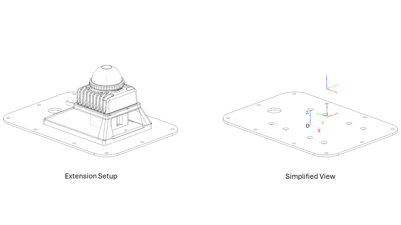
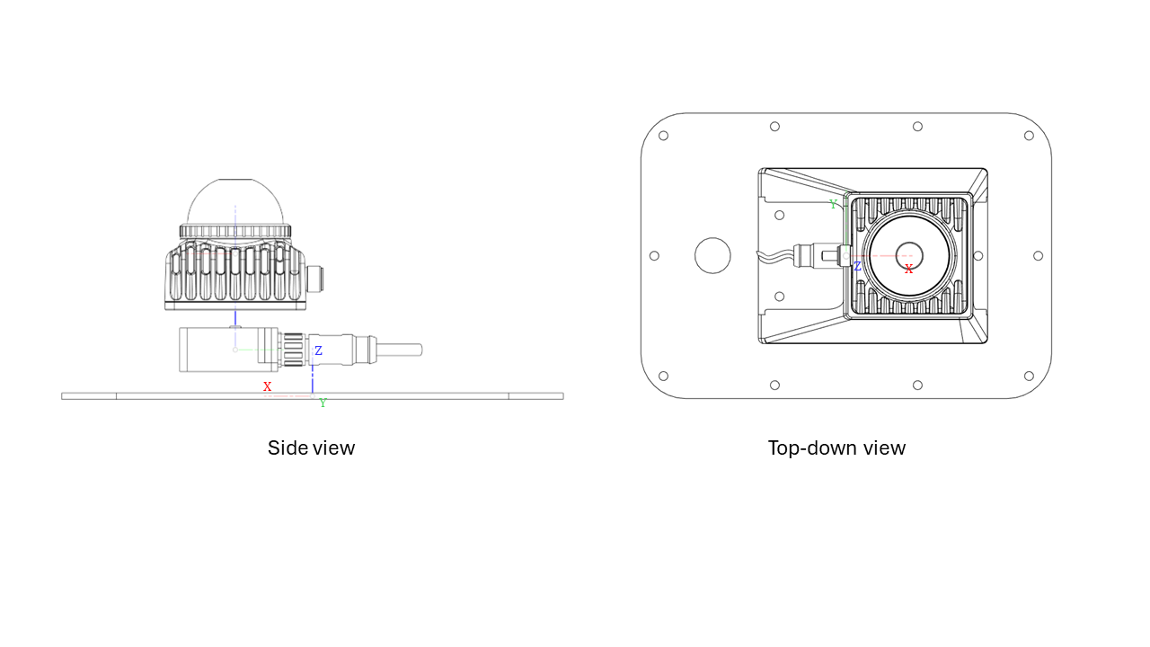
Relationship between sensors
Taking the Top Plate as the reference link for this extension, the relative position of the IMU Sensor and Lidar are as follows:
IMU Sensor: x= 35.4mm, y: 0.0mm, z: 21.3mm
Lidar: x= 35.4mm, y: 0.0mm, z: 65.4mm
Note
Do note that the Lidar has an additional integrated IMU chip (with a 3-axis accelerometer and a 3-axis gyroscope). More information can be found here