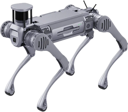
B2 Robot Dog
Revision History
Revision |
Date (DD/MM/YYYY) |
Author |
Changes |
|---|---|---|---|
1 |
31/1/2024 |
Kang Wei |
Initial release |
2 |
8/7/2024 |
Karthee |
Update Specifications & FAQ |
1. Overview
2. Specifications
Standing State |
1098mm x 450mm x 645mm |
Folded State |
880mm x 460mm x 330mm |
Net Weight (Incl. battery) |
Approx. 60kg |
Degrees of Freedom |
12 |
Maximum Speed |
3.5m/s (Limited for safety purposes) |
Operating Temperature |
-20℃ ~ 55℃, under good weather conditions |
Slope Walking Ability |
< 45° (Low Speed)
< 30° (High Speed)
|
Maximum Step Height |
< 25cm |
Jumping Ditch Width |
0.5 ~ 1.2m |
Maximum Jumping Distance |
> 1.6m |
Protection Level |
IP67 |
Model |
BT2-10 |
Weight |
12.2kg |
Capacity |
45Ah (2268Wh) |
Standard Voltage |
50.4V |
Charging Voltage |
58.8V |
Charging Current |
15A |
Operating Time |
4 - 6h |
Charging Time |
3h 20m |
Intel Core i5-1235U |
OS: Ubuntu 20.04
RAM: 8GB
Hard Drive: 512GB
|
Intel Core i7-1255U / i7-1265U |
OS: Ubuntu 20.04
RAM: 32GB
Hard Drive: 512GB
|
Nvidia Jetson Orin NX |
OS: Ubuntu 20.04
RAM: 32GB
Hard Drive: 512GB
|
Control and Perception Computing Power |
PC1 [1]: Intel Core i5
PC2 [2]: Intel Core i7
PC3 [3]: Intel Core i7 / Nvidia Jetson Orin NX
PC4 [3]: Intel Core i7 / Nvidia Jetson Orin NX
PC5 [3]: Intel Core i7 / Nvidia Jetson Orin NX
|
Perception Sensor Configuration [4] |
3D LiDAR ×1
Depth Camera ×2
Optical Camera ×2 / 1280 x 720 / 15Hz
|
External Interfaces |
1000M-Base-Ethernet ×4
USB3.0 ×4
12V ×4
5V ×1
24V ×4
BAT ×1
|
[1] Standard configuration
[2] User development
[3] Optional configuration
[4] Varies with different configurations
3. Electrical Interfaces
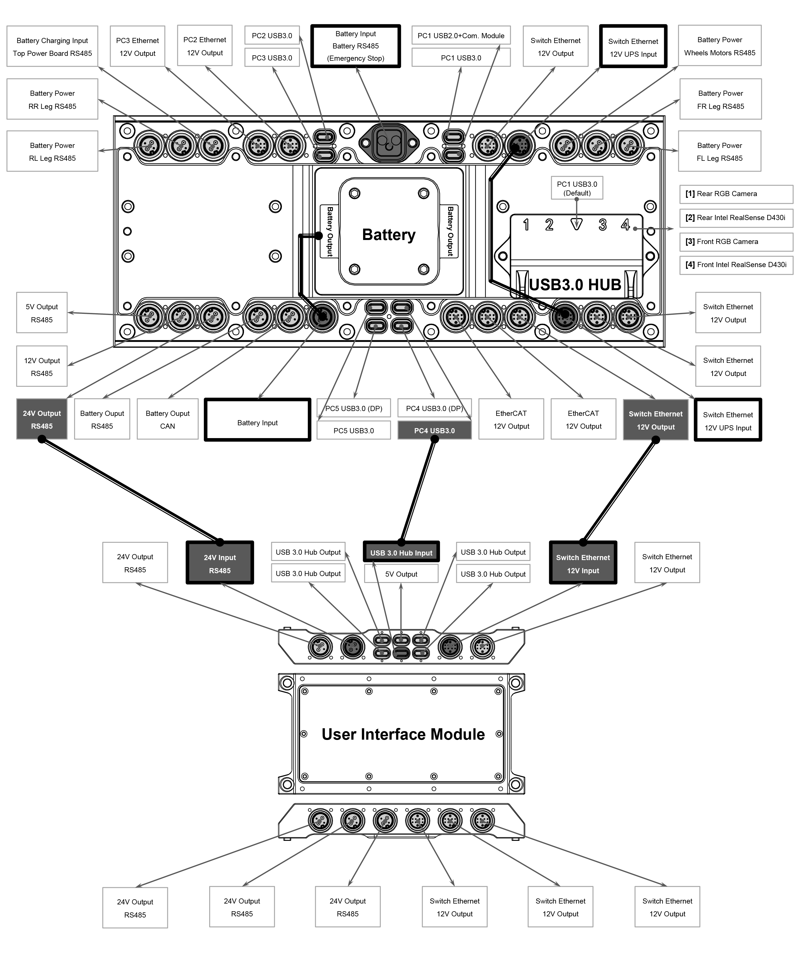
- Battery Charging Input [1]
- Top Power Board RS485 [1]
- Emergency Stop Interface [2]
|
Reserved 4-pin connector for wireless charging plate and
RS485 pins for communication with the power board.
Emergency stop interface is NOT READY for use.
|
- PC3 Ethernet
- 12V Output
|
10-pin connector with direct ethernet connection to PC3 and
12V power supply
|
- PC2 Ethernet
- 12V Output
|
10-pin connector with direct ethernet connection to PC2 and
12V power supply
|
PC2 USB3.0 |
USB-C connector with direct connection to PC2 |
PC3 USB3.0 |
USB-C connector with direct connection to PC3 |
PC1 USB2.0 |
USB-C connector with direct connection to PC1 |
PC1 USB3.0 |
USB-C connector with direct connection to PC1 |
- Switch Ethernet
- 12V Output
|
Connection to ethernet switch for communication between PCs
12V power supply
Maximum current rating: 10A
Surge current protection: 20A
|
- Switch Ethernet
- 12V UPS Input [3]
|
Connection to ethernet switch for communication between PCs and
12V UPS power input
|
- Battery Power [1]
- Wheels Motors RS485 [1]
|
Reserved port for wheeled configuration |
- Battery Power [1]
- FR Leg RS485 [1]
|
Reserved port for front right leg |
- Battery Power [1]
- FL Leg RS485 [1]
|
Reserved port for front left leg |
- EtherCAT
- 12V Output
|
EtherCAT communication protocol and 12V power supply |
PC4 USB3.0 (DP) |
Direct USB-C DisplayPort connection to PC4 |
PC4 USB3.0 |
USB-C connector with direct connection to PC4 |
PC5 USB3.0 (DP) |
Direct USB-C DisplayPort connection to PC5 |
PC5 USB3.0 |
USB-C connector with direct connection to PC5 |
Battery Input [1] |
Reserved port for internal electrical circuit |
Battery Output |
58V power supply |
- Battery Output
- RS485
|
58V power supply and RS485 communication protocol |
- 24V Output
- RS485
|
24V power supply and RS485 communication protocol
Maximum current rating: 10A
Surge current protection: 20A
|
- 12V Output
- RS485
|
12V power supply and RS485 communication protocol |
- 5V Output
- RS485
|
5V power supply and RS485 communication protocol |
- Battery Power [1]
- RR Leg RS485 [1]
|
Reserved port for rear right leg |
- Battery Power [1]
- RL Leg RS485 [1]
|
Reserved port for rear left leg |
[1] Reserved ports are designated solely for internal electrical circuit use only, not open for public acccess
[2] E-Stop interface is still in development and the use of this interface can damage the B2’s main control board.
[3] The standard B2 robot dog does not come equipped with an Uninterruptible Power Supply (UPS). However, it is available as a customizable add-on feature.
User Interface Module
The user interface module expands the interfaces available on the B2 body, allowing users to access the robot without needing to remove the panels.
(2+2) Power Line Interface
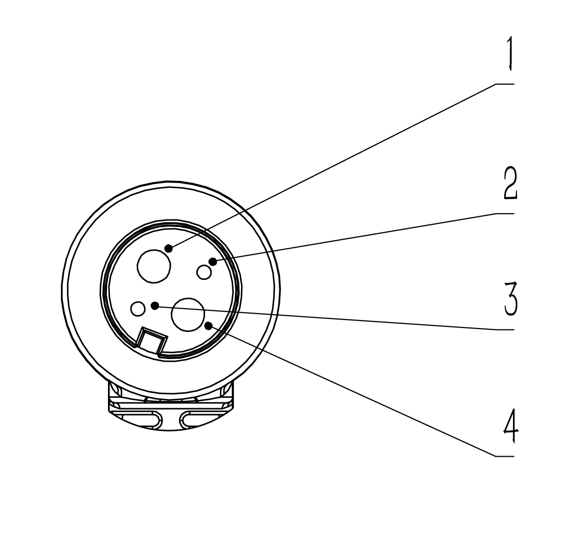
Pin |
Colour |
Interface |
|---|---|---|
1 |
Black (14AWG) |
Power- |
2 |
Red (24AWG) |
485A |
3 |
Black (24AWG) |
485B |
4 |
White (14AWG) |
Power+ |
(8+2) Signal Line Interface
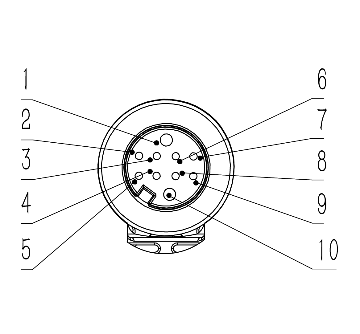
Pin |
Colour |
Interface Meaning |
T568 Standard Ethernet Cable |
|---|---|---|---|
1 |
Black |
Power- |
|
2 |
Orange |
4N |
Brown |
3 |
Purple |
4P |
White Brown |
4 |
Brown |
1P |
White Orange |
5 |
Blue |
1N |
Orange |
6 |
White |
3N |
Blue |
7 |
Green |
3P |
White Blue |
8 |
Pink |
2N |
Green |
9 |
Grey |
2P |
White Green |
10 |
Red |
Power+(12V) |
4. Resources
Basic Guides
B2 Manual: Unitree
Training Slides: B2 Customer Training
Development
SDK Support: unitree_sdk2
ROS2 Support: unitree_ros2
Mechanical
User Interface Module CAD: B2 User Interface Module STEP
5. FAQ
- Can the ports on the side of the B2 be used?
Yes, the ports on the side of the B2 robot are accessible for use. However, we strongly recommend using the ports located on the User Interface Module whenever possible. This is because using the side ports could compromise the robot’s waterproof capabilities. Users are urged to be familiar of the different ports before using them.
- What is the default speed of the B2 in AI mode?
The default is Low speed. Double click L1 to switch to High Speed.
- Can the RealSense cameras on the B2 be used for secondary development?
No, the RealSense cameras on the B2 robot are currently not accessible for users to directly control or integrate into their own development projects. These cameras are primarily used by the manufacturer to power the robot’s built-in perception features.
- Can the contact charger be used outdoors?
This contact charger is designed for indoor use. Avoid using it in wet or humid environments to prevent the risk of short circuits. Moisture can damage the charger and potentially pose a safety hazard.
- What does first foot control and second foot control represent?
First Foot control represents Normal mode, while Second Foot control reprensents AI mode. When switched on, the B2 is in AI mode (Second Foot control) by default.