UGV Development Kit
A pre-integrated compute, power and networking stack that mounts on a robot base, turning it into a development platform for research and fast prototyping. It fits a wide range of bases, and further components can be mounted on the frame as an application needs them.
Everything arrives wired, configured and tested, with drivers and sample applications already installed — you start from a working platform rather than an assembly job.
Two generations are in the field. The quickest way to tell them apart is the onboard computer: a NanoPC is v1.0, a reComputer J4012 is v1.1. See Specifications for the full difference.
- v1.1
- v1.0
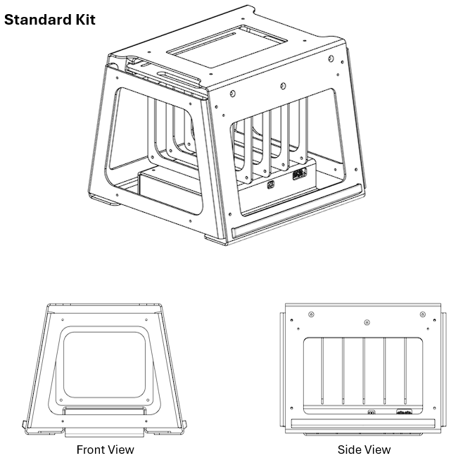
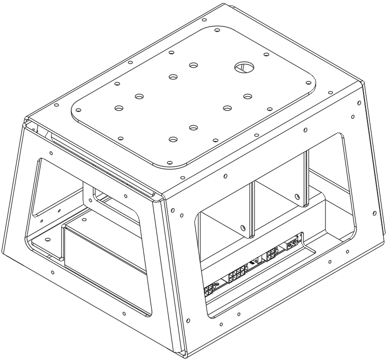
Getting started
The kit is delivered configured, so bring-up is mostly a matter of reaching it:
- Power the base and let the kit come up with it.
- Join the kit's WiFi, broadcast by its built-in router.
- SSH to the onboard computer — credentials and the address are on your handover note, not published here.
- Configure any cameras you have fitted.
The Getting Started guide covers all of this in detail, including putting the kit onto your own WiFi so it has internet access.
Key information
Related resources
| Resource | What it is | Where |
|---|---|---|
| 3D mapping sample | LIO-SAM setup, pre-installed | wr_devkit_mapping |
| Navigation sample | ROS 2 Nav2 setup, pre-installed | Nav2 Sample Setup |
Installing Weston Robot packages on the onboard computer? Add our package repository first: Weston Robot Apt Source.
The ROS drivers cover components in the base configuration and the extension modules we supply. The open-source mapping and navigation stacks are installed for demonstration and provided as is — treat them as a working starting point to modify, not as a supported product.
What's in the kit
Base configuration, pre-integrated and wired:
- Onboard computer:
- NanoPC on v1.0
- reComputer J4012 on v1.1
- Power Regulator v2.X
- Industrial 5G / WiFi router
Additional computers can be added for heavier workloads:
- Jetson Orin NX
- Mini PC (Intel Core i7)
Extension modules available on top of the base configuration:
| Module | Documented |
|---|---|
| Livox Mid-360 LiDAR + IMU | Mid-360 extension |
| Vision Sensor Kit | Vision extension |
| Ouster OS1 LiDAR + IMU | — |
| RTK / GNSS module | — |
| Ultrasonic sensor array | — |
The kit can also be customised with components of your choice — contact us with your requirements.
Logins and IP addresses
The router runs the kit's internal network on 10.10.0.0/24, with addresses assigned by role:
| Device type | IP range |
|---|---|
| Onboard computers | 10.10.0.10 – 10.10.0.20 |
| Navigation sensors | 10.10.0.30 – 10.10.0.40 |
| Application sensors | 10.10.0.100 – 10.10.0.120 |
This is the convention we configure to, and it is a recommendation rather than a requirement — you can readdress the kit to suit your network. The actual addresses and login credentials for your unit are on the handover note supplied with it.
The router's own web interface is at 10.10.0.1 — see the router page for its configuration.
Electrical interfaces
Power is distributed by a built-in Power Regulator v2.X, which is where you connect payloads.
| Output | Voltage | Max current | Power |
|---|---|---|---|
| 19 V | 19 V | 8 A | 150 W |
| 12 V | 12 V | 10 A | 120 W |
| 5 V isolated | 5 V | 4 A | 20 W |
| 12 V isolated | 12 V | 3.3 A | 40 W |
Input is 18–32 V at up to 20 A. Fusing, connector types, the CANopen control interface and the channel-switching behaviour are on the Power Regulator page — including the fact that every channel is off by default at power-on, which is the first thing to check if a payload appears dead.
- v1.1
- v1.0
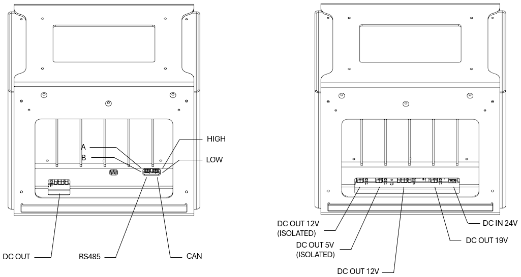
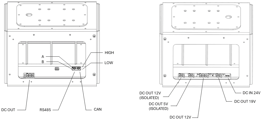
Specifications
The generations differ in the onboard computer and the frame; everything else above applies to both.
| v1.0 | v1.1 | |
|---|---|---|
| Onboard computer | NanoPC | reComputer J4012 — GPU-capable |
| Dimensions | 310 × 280 × 200 mm | 300 × 304 × 250 mm |
| Dimensions with extension layer | — | 300 × 345 × 366 mm |
| Dry weight | ~3 kg | ~3 kg, up to ~4 kg with the extension layer |
| Extension layer | Not available | Optional |
| Side doors | No | Yes |
The practical consequence: v1.1 is the one to use for perception workloads, because the J4012 has a GPU where the NanoPC does not. For base driving, teleoperation and sensor bridging, either is adequate.
Guides for this product
| Guide | What it covers | Reach for it when |
|---|---|---|
| Getting Started | WiFi, SSH access and camera configuration | Setting the kit up for the first time |
| Component re-configuration | Opening the frame, removing latches and the hardware rack | Adding, moving or servicing components inside the kit |
| Nav2 sample setup | Cartographer and RTAB-Map mapping and navigation | Running the pre-installed navigation demo |
| Livox Mid-360 extension | Specifications and reference frames for the LiDAR module | Fitting or calibrating the Mid-360 |
| Vision extension | RealSense D435i and RGB camera specifications and frames | Fitting or configuring cameras |
Troubleshooting & FAQ
A payload connected to the regulator has no power
Every regulator channel is off by default at power-on. Switch it on, or set the power-on defaults — see Set the default state of each channel.
I cannot reach the onboard computer at the address given here
The ranges above are a convention, not a guarantee. Use the addresses on your handover note.
Which generation do I have?
Look at the onboard computer: a NanoPC is v1.0, a reComputer J4012 is v1.1. The frame is the other tell — v1.1 has removable side doors and can take an extension layer.
Support
Collect the serial number, the handover note and logs before raising a ticket — Before you contact us lists what helps and includes the commands to gather it.