NanoPC-based onboard computer
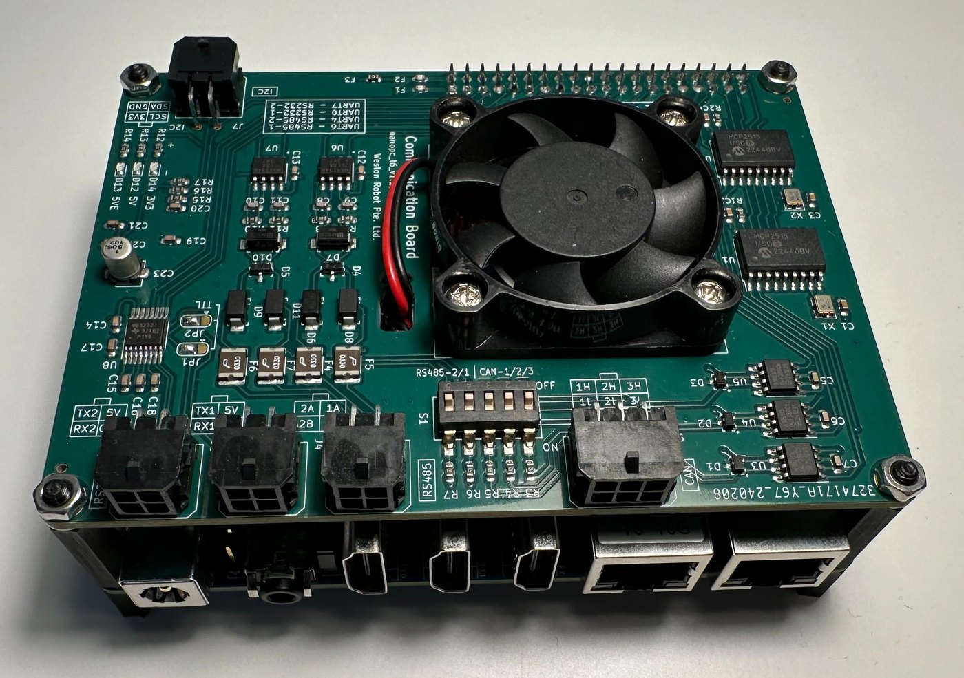
An onboard computer for our robot platforms, built on the FriendlyELEC NanoPC-T6 (Rockchip RK3588). We extended the base board with industrial ports — CAN, RS485 and RS232 — so it can interface directly with robot bases and the sensors commonly fitted alongside them, without a USB adapter in the path.
Drivers for those ports are pre-configured under Ubuntu 22.04, so the interfaces are present on first boot. What is not obvious from the board itself is how each port appears to software; that mapping is in Electrical interfaces and is the main reason to read this page.
FriendlyELEC's NanoPC-T6 wiki documents the base board only — it does not cover the industrial port extensions we add, which are documented here.
Getting started
- Mount the board where it has airflow — it is actively cooled by a 5 V fan.
- Power it through the 5.5 × 2.1 mm DC jack. It accepts 5–20 V; 12 V is recommended.
- Wire your devices to the industrial ports, following the silkscreen labels.
- Bring the interfaces up — CAN needs an explicit
ip linkbefore it exists to software, and the serial ports are not named after their silkscreen labels. Both are covered in Electrical interfaces.
Most robot bases we supply can feed 12 V directly. Where the platform's rail is higher, or shared with motors that pull it down under load, take the computer from a regulated output instead — the Power Regulator v2 exists for this.
Key information
Related resources
| Resource | What it is | Where |
|---|---|---|
| Base board wiki | FriendlyELEC's NanoPC-T6 documentation — base board only, not our extensions | NanoPC-T6 wiki |
Installing Weston Robot packages on the computer? Add our package repository first: Weston Robot Apt Source.
Electrical interfaces
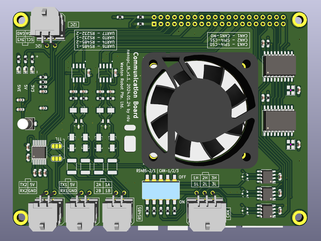
The silkscreen labels the ports; it does not tell you which device node each one is. Follow the silkscreen to wire your devices, then use the mapping below to reach them.
Serial ports
| Silkscreen | Device node |
|---|---|
| RS232-1 | /dev/ttyS0 |
| RS232-2 | /dev/ttyS7 |
| RS485-1 | /dev/ttyS6 |
| RS485-2 | /dev/ttyS4 |
The jumper solder pads JP1 and JP2 select the signalling on RS232-2:
- bridge the middle pad to the side marked TTL — TTL UART
- bridge the middle pad to the other side — RS232
- no bridge — the port provides power only, and no signal is transmitted
Either way the port is reached at /dev/ttyS7. If a device on RS232-2 is powered but silent, check this first.
CAN interfaces
Three CAN interfaces are fitted, with transceivers. They exist as network interfaces and must be brought up before use — adjust the bitrate to match your devices:
sudo ip link set can0 up type can bitrate 500000
sudo ip link set can0 txqueuelen 1000
To bring them up automatically at boot, add this to /etc/network/interfaces:
auto can0
    iface can0 inet manual
    pre-up /sbin/ip link set can0 type can bitrate 500000
    up /sbin/ifconfig can0 up
    post-up /sbin/ip link set can0 txqueuelen 10000
    down /sbin/ifconfig can0 down

auto can1
    iface can1 inet manual
    pre-up /sbin/ip link set can1 type can bitrate 500000
    up /sbin/ifconfig can1 up
    post-up /sbin/ip link set can1 txqueuelen 10000
    down /sbin/ifconfig can1 down

auto can2
    iface can2 inet manual
    pre-up /sbin/ip link set can2 type can bitrate 500000
    up /sbin/ifconfig can2 up
    post-up /sbin/ip link set can2 txqueuelen 10000
    down /sbin/ifconfig can2 down
CAN and RS485 termination is selected by DIP switch and is disabled on delivery. A bus that works over a short bench cable and fails on the robot is usually missing termination.
The 5 V output rail sits behind a resettable fuse rated at 300 mA. Keep the total draw of everything you power from it under that figure, or the rail will cut out and reset — which presents as an intermittent sensor rather than a power fault.
Specifications
Figures for the unit as we supply it. Anything not listed here is on the base board wiki.
| SoC | Rockchip RK3588 |
| RAM | 8 GB or 16 GB LPDDR4X (64-bit) |
| Storage | 128 GB or 256 GB eMMC, plus microSD (card not included) |
| Ethernet | 2 × 2.5 GbE (PCIe) |
| USB | 1 × USB 3.0 Type-A · 1 × full-function USB Type-C (USB 3.0, DP out to 4Kp60) |
| Video | 1 × HDMI input (to 4Kp60) · 2 × HDMI output |
| Audio | 3.5 mm stereo output · 2.0 mm PH-2A analogue microphone input |
| Industrial ports | 3 × CAN (with transceivers) · 2 × RS485 · 2 × RS232 |
| Power input | 5.5 × 2.1 mm DC jack, 5–20 V (12 V recommended) |
| Operating temperature | 0 °C to 70 °C |
| Cooling | Active — 1 × 5 V fan |
| Operating system | Ubuntu 22.04, Linux kernel 5.10 |
Troubleshooting & FAQ
A device on RS232-2 has power but no data
The JP1/JP2 jumper is either unbridged, or bridged for the wrong signalling. See the note above.
A CAN interface does not appear
CAN interfaces have to be brought up explicitly — ip link set can0 up — and do not persist across a reboot unless you have configured /etc/network/interfaces. See CAN interfaces.
A sensor works on the bench but drops out on the robot
Two common causes: missing bus termination (off by default), or the 5 V rail's 300 mA fuse tripping under the combined load.
Support
Collect the serial number, OS image version and logs before raising a ticket — Before you contact us lists what helps and includes the commands to gather it.