Map editor
The Map Editor turns a 3D scan of a building into a site map. It runs as five numbered stages, worked left to right.

You are not marched through them. Any stage can be revisited once its prerequisites are met, so going back to re-crop a scan after placing a few nodes is normal rather than a restart. A stage that cannot yet be opened says which prerequisite is missing rather than simply refusing:
| Stage | Opens once |
|---|---|
| 1 · Load Map Data | Always — it is the starting point |
| 2 · Prepare Data | A point cloud is loaded |
| 3 · Setup Levels | A point cloud is loaded |
| 4 · Edit Map | At least one level is defined |
| 5 · Export | At least one node exists |
Work is saved as you go, and the header shows when it last was. It lives in your browser rather than on a server, so it is yours until you push it — though the point cloud is loaded again each session.
1 · Load Map Data
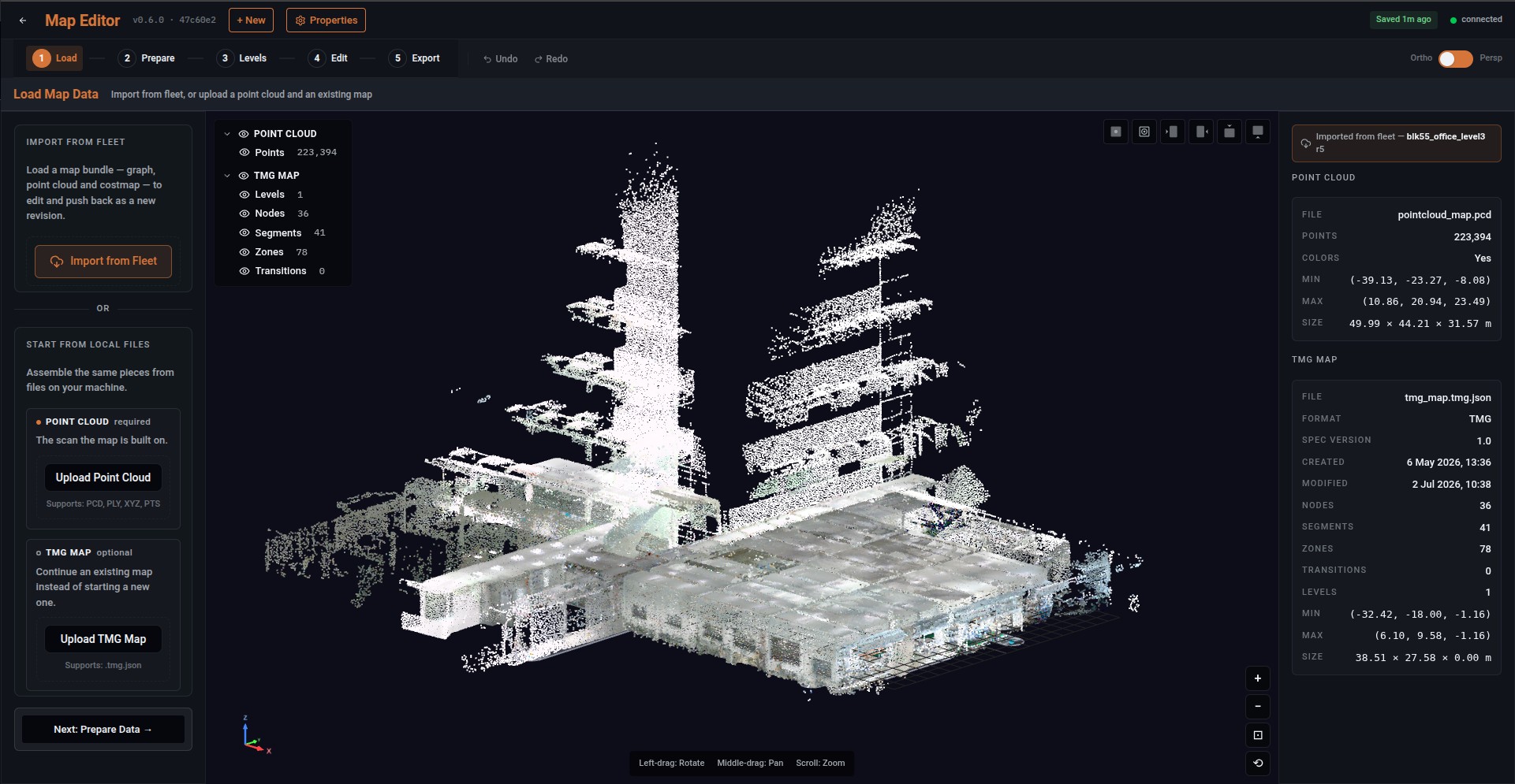
Import from Fleet pulls an existing map bundle — the graph, its point cloud and its occupancy map — down to edit and push back as a new revision. The header then names the map and revision you are working from, so there is no doubt which one it is.
Start from local files assembles the same pieces yourself. A point cloud is required — the scan the map is built on, in PCD, PLY, XYZ or PTS, with colour if the scan carries it. A TMG map is optional, and loading one continues an existing map rather than starting a new one, which is how you re-author a map against a fresh scan.
If you do not have that point cloud yet, Manifold Scanner Guides covers capturing a site with a handheld scanner and exporting a .pcd from it. Name that file pointcloud_map.pcd.
Look at the cloud before you start drawing on it. A scan that is tilted, warped, doubled, disconnected or badly incomplete produces a map that looks reasonable here and navigates badly, and every stage after this one inherits the problem. The scanner guides list what to reject and why; the cheapest moment to send a bad scan back is before a single node is placed.
Check the other direction too: a cloud can be too sparse to localise against. A robot matches what it sees to the map, so the permanent structure of the site — walls, columns, fixed racking — is what it needs. A repetitive building filtered down to bare geometry can look tidy here and leave a robot unable to tell one corridor from the next.
It can also be too heavy. What you build here does not stay here: the bundle is uploaded to the Robot Management Toolbox and then pushed down to every robot that works the site, all of it over Wi-Fi. A cloud that is merely slow to draw on a workstation is an expensive thing to move over a site network, repeatedly.
For reliable operation, keep the point cloud below 200 MB and the complete map bundle below 300 MB. Maps that exceed these recommendations may require additional optimization before they can be used reliably with the Deployment Toolbox. Working inside them is also ordinary economy: density beyond what makes the building legible costs upload time and gains the robot nothing. The scanner guides reduce the cloud before the handoff for this reason.
Once something is loaded, the panel reports what you have: the point cloud's file, its point count and its extent in metres; and for a map, its format and spec version, when it was created and last modified, and how many nodes, segments, zones, transitions and levels it holds. Read those counts before you start editing — they are the quickest way to notice you have opened the wrong map, or an older revision than you meant.
Reach for Import from Fleet whenever the site already has a map. Sites change, and whoever updates one needs to start from what is actually live rather than a copy on a laptop that may be several revisions behind — and nothing will tell you that it is.
2 · Prepare Data
Clean up the scan before anything is drawn on it.
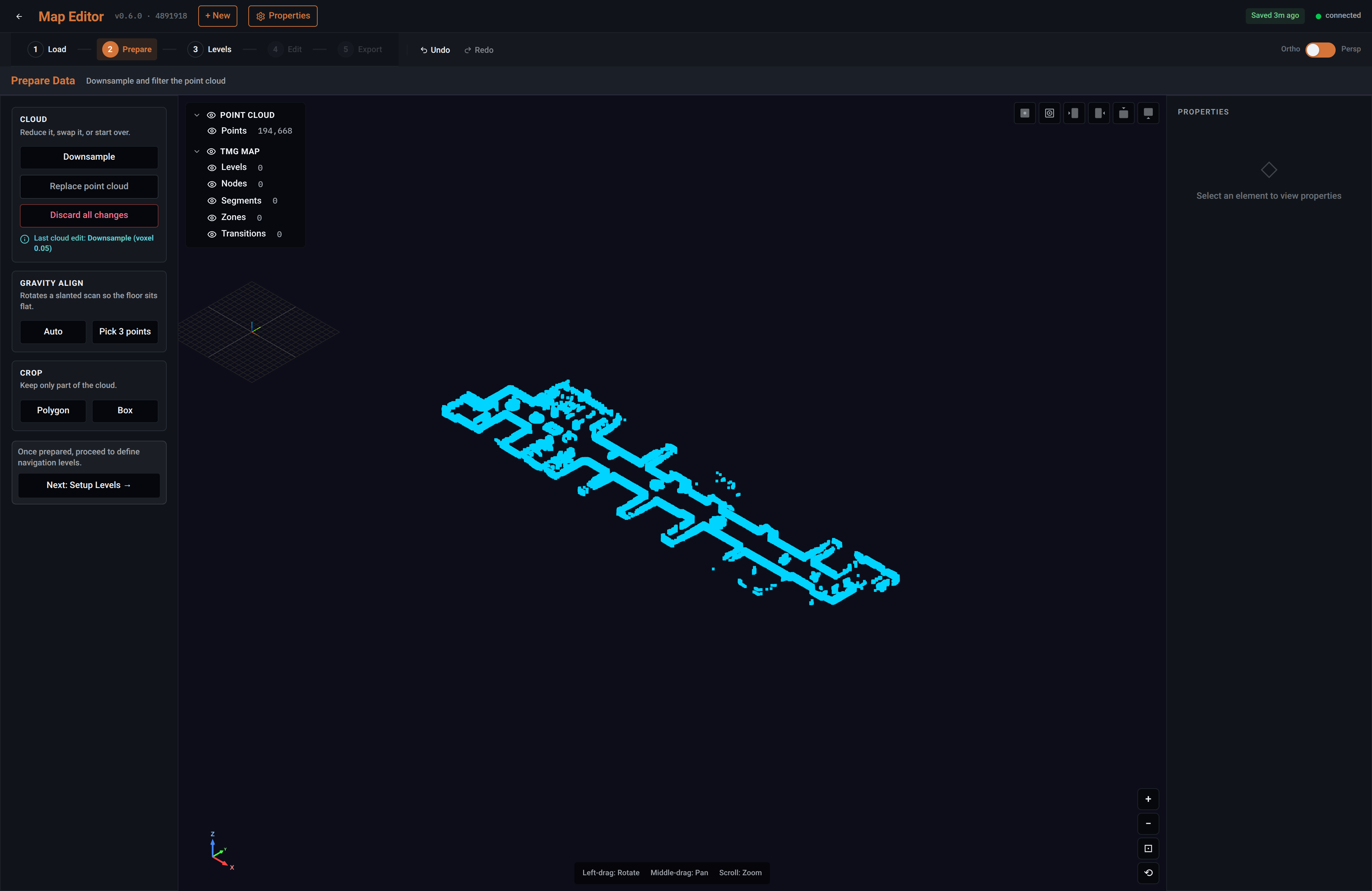
| Operation | What it does |
|---|---|
| Downsample | Merges points into a grid of cubes and keeps one per cube |
| Gravity align | Rotates a slanted scan so the floor sits flat — automatically, or by picking three points on a surface you know is level |
| Crop | Keeps only part of the cloud, by polygon or by box |
Downsample first. A raw scan is slow to draw on, and the editor says so when it is given a large one. You choose the cube size: the office scan above went from 555,150 points to 194,668 at a 5 cm grid — enough detail to place a map against, and far quicker to work with.
This stage decides the quality of everything after it. A scan that is subtly tilted produces a map that looks correct and navigates badly: where the floor sits, where the nodes and zones you later place come to rest on it, and whether routes solve all follow from getting this right. It is the cheapest stage to redo and the most expensive to skip.
3 · Setup Levels
Identify the floor the map is built on. Every node and zone belongs to a level.
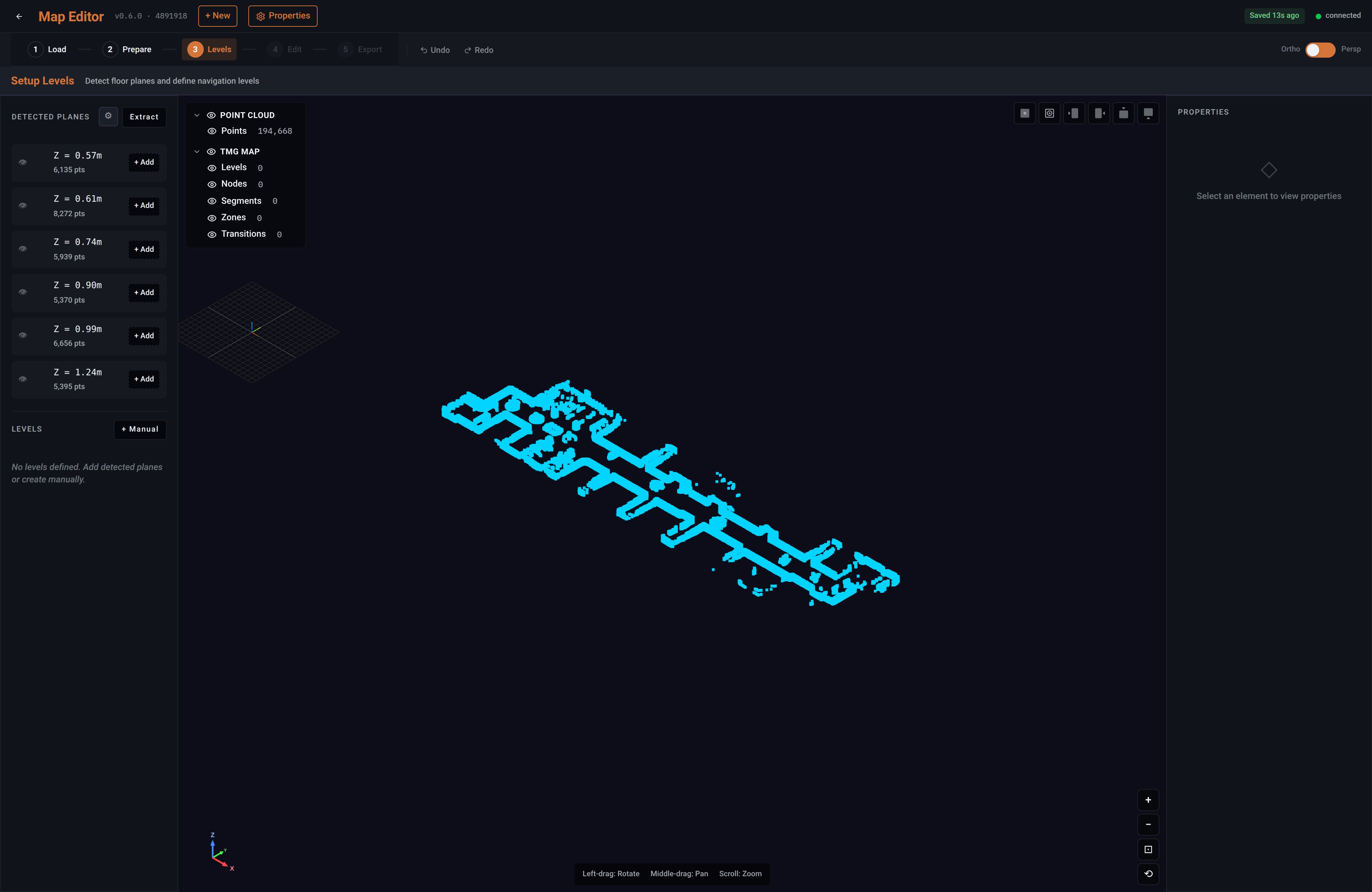
Extract finds the horizontal planes in the scan and lists them by height, each with the number of points supporting it. You add the one that is the floor — and that point count is how you tell a real floor from a run of desks at a consistent height.
For a single-level site this stage is short: there is one level, and everything on the map belongs to it.
When the floor does not appear
Extraction works from the points it has. If the level you expect is not in the list, the usual reason is that too few points landed on it for a plane to be detected — a floor that was only crossed quickly, or largely occluded by furniture, may simply not have enough support.
That is not by itself a verdict on the whole map. + Manual under LEVELS defines a level directly, and a site whose floor had to be added by hand can still be perfectly workable.
Adding the level by hand gets the workflow moving. It says nothing about whether the point cloud under it is accurate or complete — and a scan thin enough to miss its own floor is worth a second look. If the cloud also looks tilted, warped, doubled or misaligned, re-scan rather than working around it; the Manifold Scanner Guides cover what to check.
Multiple detected levels are not multi-floor deployment
Extraction will happily list several height bands, and a building with more than one storey in the scan will produce more than one candidate plane. That is the tool reading geometry.
It does not mean a robot can be deployed across those floors. Treat extra detected planes as candidates to choose the floor from, not as floors you can dispatch to — see whether a deployment can span floors or elevations.
The occupancy map
Adding a level offers a second thing: a top-down occupancy map generated from the cloud for that level. It is the flat picture of what is free and what is blocked, and it is what the fleet later draws underneath the graph so a node can be read against the building rather than as a coordinate.
You choose the slice it is built from — a minimum and maximum height above the floor — along with its resolution and how many points a cell needs before it counts as occupied. Taking the slice at roughly robot height is what keeps a ceiling fixture out of the picture and a chair leg in it.
One is generated per level, and it travels with the map.
4 · Edit Map
This is where the map itself is drawn: the nodes a robot can be sent to, the segments it may travel along, and the zones that apply rules.
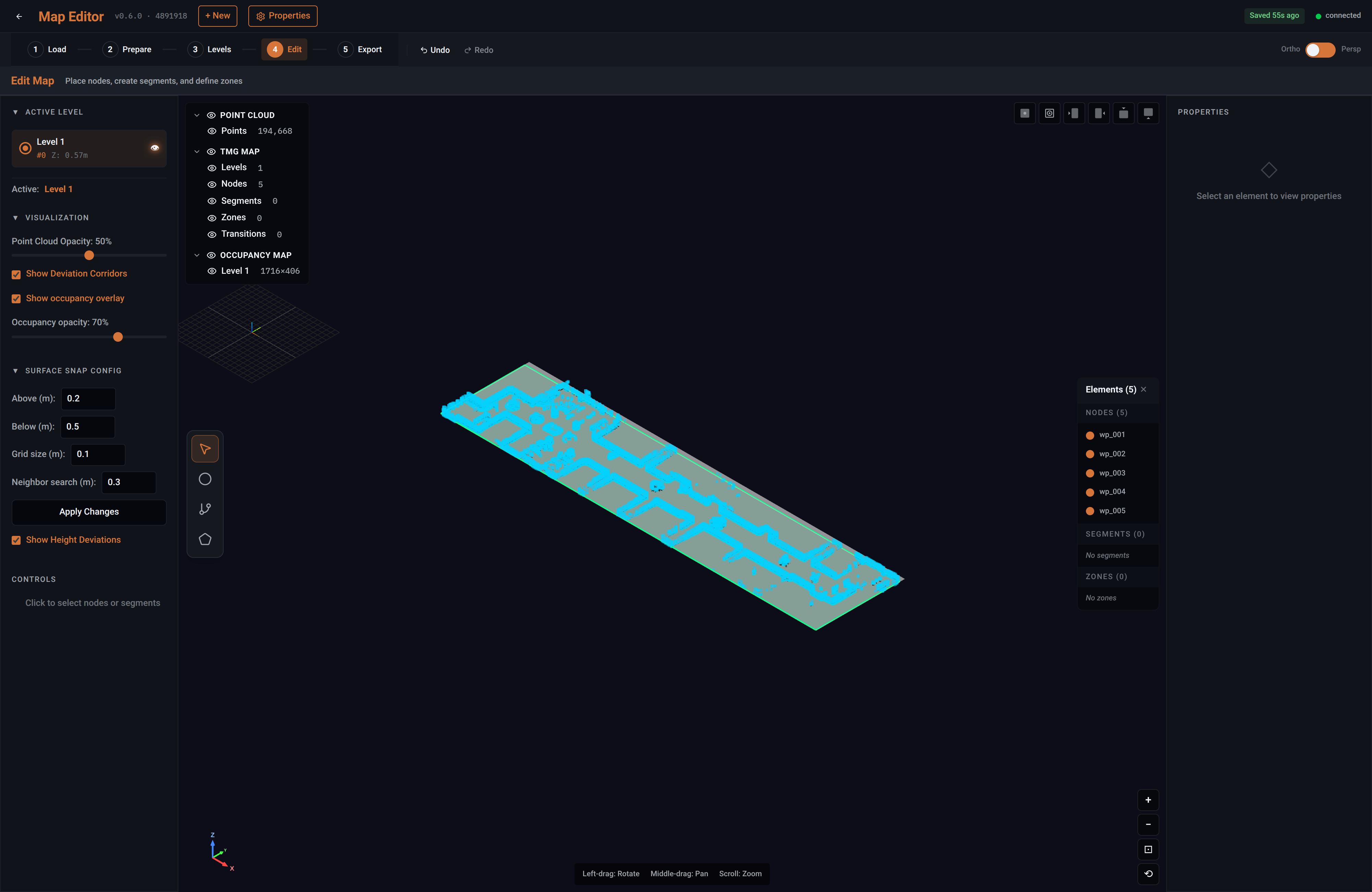
The tools
Four tools sit on the view, and each tells you how it is driven while it is active.
| Tool | How it works |
|---|---|
| Select | Click a node or segment to select it. Shift-click to select several |
| Node | Double-click on the level to place one; drag it to move it |
| Segment | Click one node to start, then another to connect them. Via points can be dragged to shape the path between |
| Zone | Draw a boundary, for the rules that apply inside it |
Every action is undoable, and the map is saved as you go.
What you draw against
The point cloud, the occupancy map and the level each have their own visibility and opacity. You can work against the raw scan, against the flat occupancy picture, or both at once — and the choice matters more than it sounds, because placing a node against an empty grid is how a node ends up somewhere a robot cannot reach.
The scan is the more truthful of the two: it shows the clutter that the occupancy slice may have cut away. The occupancy map is the easier to read. Most people use the scan faded behind the occupancy map.
Selecting and adjusting
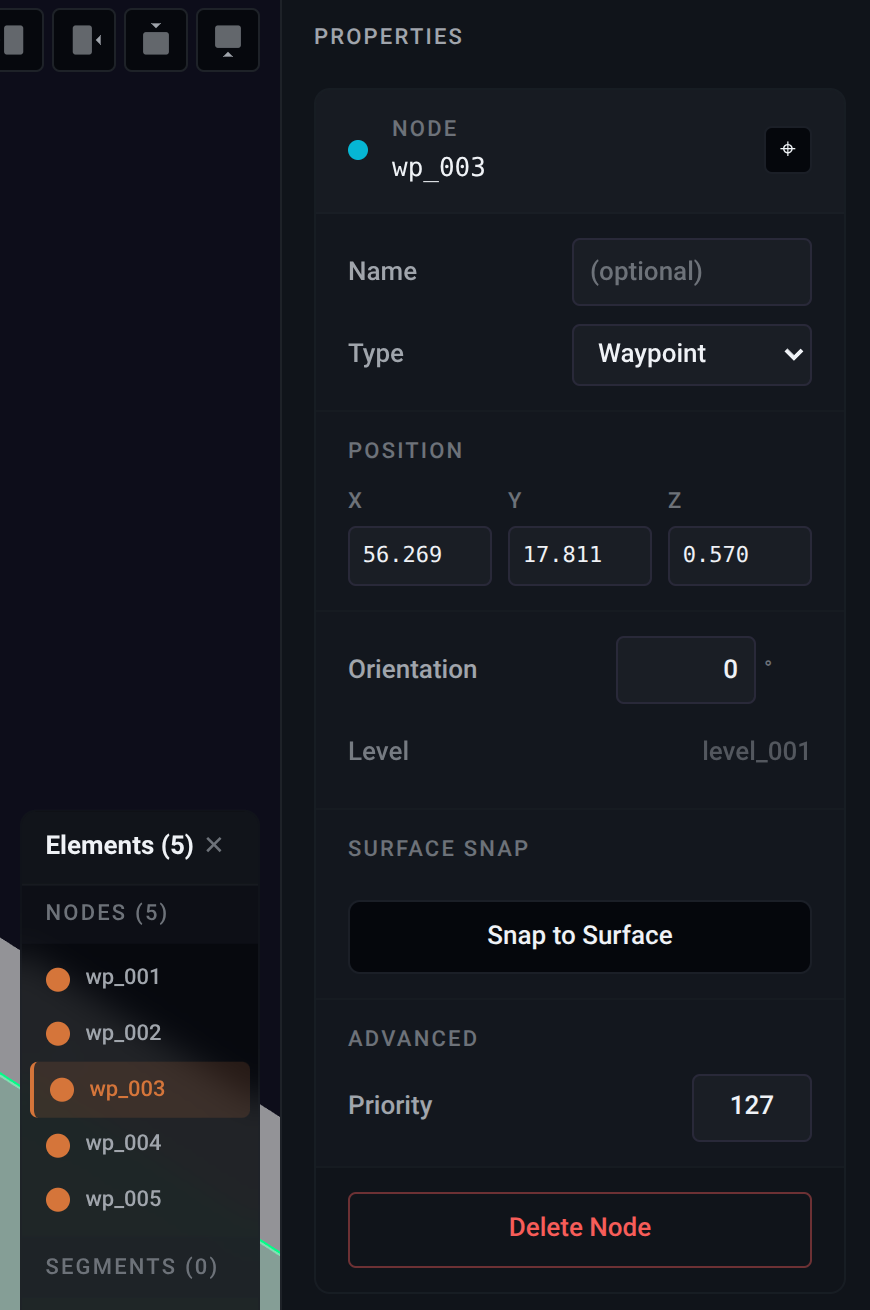
The elements list is a running index of everything on the map, grouped by kind. Selecting from it selects on the map, and the focus control jumps the view to whatever is selected — which is how you find one node among sixty rather than hunting for it.
The properties panel is where a selected element is adjusted:
| Field | What it sets |
|---|---|
| Name | Optional, and worth setting — a map of wp_001 through wp_024 is searchable and tells nobody anything |
| Type | Whether the node is an ordinary waypoint or a charging station |
| Position | X, Y and Z, editable directly when a click is not precise enough |
| Orientation | Which way the robot faces on arrival, in degrees |
| Level | Which level the element belongs to |
| Priority | Advanced; leave it alone unless you have been told otherwise |
Position and orientation being editable matters more than it seems. Clicking is fine for placing a node roughly; typing is how you put one exactly at the middle of a doorway, or make two facing points face the same way.
Surface snapping
Surface snapping is what settles a node onto the floor instead of leaving it floating, and a node that is floating is a node a robot cannot be sent to.
It works from a height grid computed against the active level, and you control how it looks:
| Setting | What it does |
|---|---|
| Above and Below | How far above and below the level to search for a surface |
| Grid size | How finely the surface is sampled |
| Neighbour search | How far around a point to look when working out the surface height |
Widening the search range is the fix when nodes will not settle; narrowing it is the fix when they settle onto the wrong thing. Show height deviations draws how far each node sits from the level, which is how you spot the one that snapped to a desk rather than the floor.
Placing nodes and segments is not the same as having a route. Segments are what a route is computed over, so two segments that appear to meet on screen but do not share a point produce a map that looks connected and does not solve. The Map inspector is where that is checked, and it is worth checking before you export.
5 · Export
Validate the map, review what it contains, and send it somewhere.
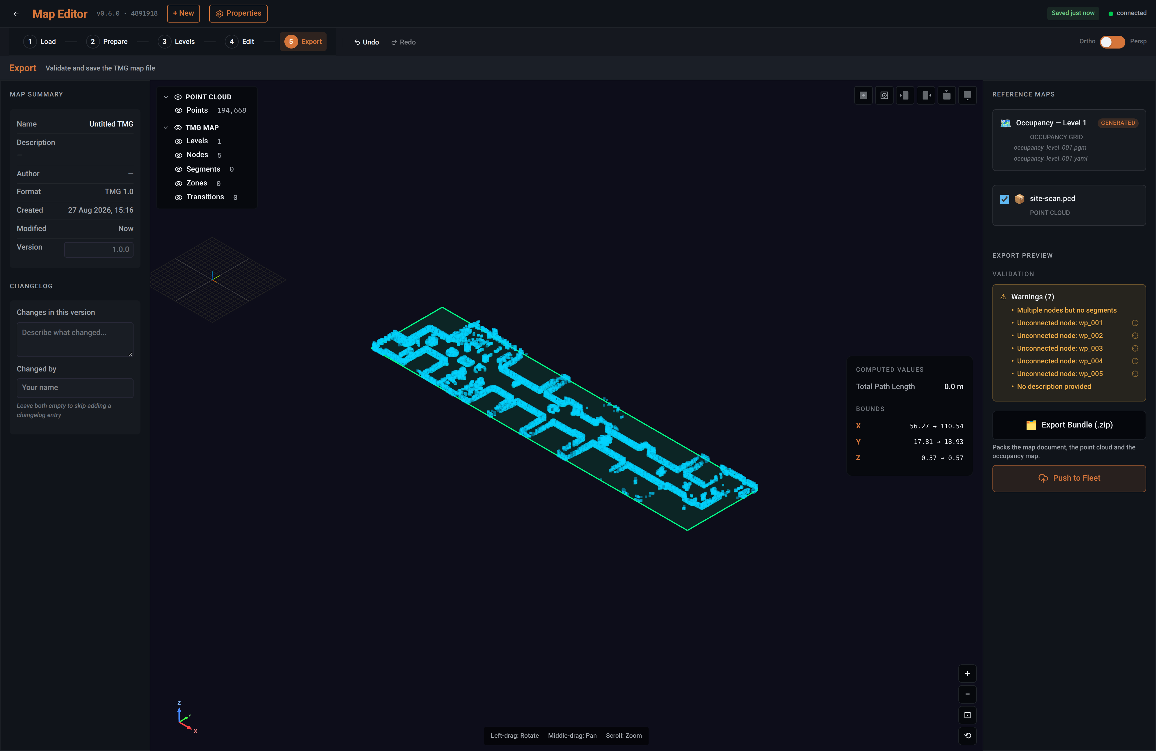
Validation is the point of the stage. It reports what is wrong by name rather than in general — the map above is warned that it has multiple nodes but no segments, and each unconnected node is listed individually. A warning is not a refusal, but shipping past one is a decision rather than an oversight.
Validation checks the map against itself, not against the building. It catches a node nothing connects to; it cannot catch a segment drawn through a wall the scan missed, or a floor that sits 30 cm below where the robot finds it. Clean validation means the map is internally coherent — the question of whether it describes the site correctly is settled by driving on it, and only then.
The stage also shows what the bundle will carry: the map document, the point cloud, and the occupancy map generated for each level, written as a standard grid and its accompanying metadata. Keep the complete bundle below 300 MB for reliable operation.
A changelog entry belongs to the version, not to the file. The stage asks what changed and who changed it, and leaving both empty skips the entry — which is worth not doing, because it is the record that explains a revision to whoever opens it next.
From here the map can be exported as a bundle — a .zip packing the map document, the point cloud and the occupancy map — or pushed to the Robot Management Toolbox, which is the route that leads to robots.
Name the TMG document tmg_map.tmg.json, alongside pointcloud_map.pcd for the cloud it was drawn against, so a site's files can be picked up months later without guesswork.
Pushing to the fleet
A finished map does nothing until it reaches robots, and the Robot Deployment Toolbox performs only the first step of that journey.
What the push asks for
Pushing sends the map into the Robot Management Toolbox. The push asks for four things:
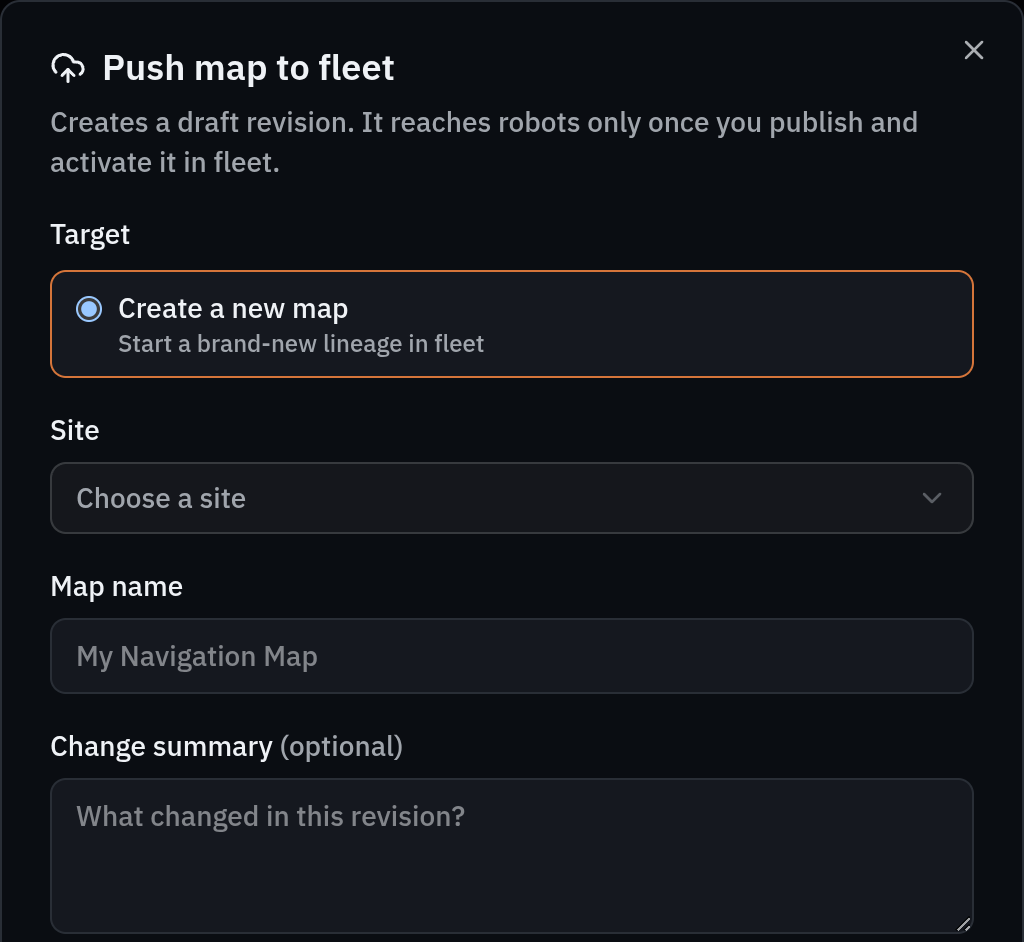
| Field | What it decides |
|---|---|
| Target site | Which site in the fleet the map belongs to |
| New map, or an existing one | Whether this starts a new map, or adds a revision to one that already exists |
| Map name | What the map is called, when it is a new one |
| Change summary | What changed in this revision |
The change summary is worth writing properly. It is what a revision list shows months later, and the difference between "updated" and "moved the charging point after the racking was re-laid" is the difference between a history someone can read and a column of dates.
Choosing an existing map rather than a new one is what keeps a site's revisions together as one history. Starting a new map each time produces a site with several unrelated maps and no way to see how any of them changed.
What happens next
A pushed map arrives in the fleet management system as a draft revision. It is stored, and it is not in front of anyone.
Two further steps, both taken by a person in the fleet management system, turn it into the map robots run:
| Step | Who | What it does |
|---|---|---|
| Push | This tool | Creates the draft revision |
| Publish | Site Admin or Tenant Administrator | Marks the draft a finished revision |
| Activate | Site Admin or Tenant Administrator | Makes it the revision robots are given |
This tool stops at the draft. It cannot publish, it cannot activate, and it never talks to a robot at all. There is no path from here to a machine in the field.
That is a boundary between the two tools rather than between two people: the same person who drew the map can publish and activate it. If your process needs a second person to review a map before robots use it, that has to come from your process.
How a map reaches a robot shows the whole path in one diagram, and Catching a robot up to the map covers what happens to robots once a revision is activated.
What activation costs a robot
Worth knowing before you push, because it shapes when the rest of the change should be scheduled: applying a new map to a robot restarts its navigation and makes it re-acquire localisation, and its missions are locked until it confirms the new map.
So a map change is not a background event at the site. Push whenever the work is done; time the activation.
The map is validated by driving on it
Everything in this tool checks the map against itself. A cloud that imported, levels that extracted, a graph that validated and a revision that published all say the artifacts are coherent — none of them says the robot will work.
The final validation is navigation. If a robot cannot localise reliably, or drifts off segments, or fails to reach nodes it should reach, then the map or the scan behind it needs revisiting, however clean it looked here. That is worth planning for: the first activation on a new site is a test, not a delivery.
Where the problem traces back to the scan rather than the drawing — a tilted or warped cloud, geometry that was never captured — the fix is upstream, in the Manifold Scanner Guides.
Common questions
A stage will not open
Each one has a prerequisite, and the stage says which is missing. Prepare and Levels need a point cloud, Edit needs at least one level defined, and Export needs at least one node.
How do I place a node exactly?
Click to place it roughly, then type its position and orientation in the properties panel. Clicking is for approximate; typing is for the middle of a doorway.
My nodes are sitting above or below the floor
Surface snapping settles them onto the level, and it looks a set distance above and below to find it. Widen that range, or check the scan was levelled properly in Prepare — a tilted scan puts the floor where the nodes are not.
Can I go back and re-crop the scan after placing nodes?
Yes. Stages are revisitable once their prerequisites are met, so returning to Prepare is normal rather than a restart.
I pushed a map but the robots have not changed
Expected. Pushing creates a draft in the Robot Management Toolbox; someone there has to publish it and then activate it. Until then robots keep the map they have.
Can I change a map without this tool?
A Site Admin or Tenant Administrator can adjust a site's saved locations in the Robot Management Toolbox. Changing the scan, the levels, the graph or the zones is this tool's job.
My site has two floors
The supported model is one deployment level on one physical floor, and that floor need not be flat — slopes and ramps the robot can traverse are ordinary. Two elevations joined by a continuously traversable route may also work as one deployment, while a steep flight of stairs divides them. Whether a deployment can span floors or elevations covers what to check, and says why the route has to be tested rather than judged from a figure.
Why does my map have so many zones?
Most were generated rather than drawn: one around every node and one along every segment. A twenty-four-node site with a single hand-drawn keep-out area still holds fifty-six zones.